
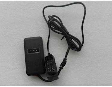
GPS Tracker
User Manual
For car with OBD port
 Please read the manual carefully before use
the GPS Tracker so that you can install
the device correctly and activate it quickly on the internet. The outlook and
true color are subject to the actual product.
Please read the manual carefully before use
the GPS Tracker so that you can install
the device correctly and activate it quickly on the internet. The outlook and
true color are subject to the actual product.
1.Accessories:


2. Technical parameter
1).GSM:850/900/1800/1900 Quad band
2).GPRS: Class12, TCP/IP
3).Working Voltage:9-24V DC
4).Working current:≈22mA (12vDC)
5).Working current:≈12mA (24vDC)
6).GPS locating time:Cold start≈38s(Open sky)
Warm start≈32s
Hot start≈2s(Open sky)
7).GPS Precision:10m(2D RM)
8).Working temperature:-20℃~+70℃
9).Working humidity:20%~80%RH
10).Measurement:87(L)×43(W)×14(H)mm
3.Out look

4.Device status indicators
4.1Connect DC 9-24V power supply and the red LED will light continuously.
4.2The green LED glistens when searching the GPS signals. When GPS works, the LED lights continuously.
4.3The intermediate blue LED (GSM signal state)
GSM signal is normal, blue LED light long bright. No GSM signal, the blue LED flashes.
GPS LED not fixed, flashes(0.2 sec/2 sec),Positioning long bright;
GSM LED no signal, flashes(0.2 sec/2 sec),Signal normal long bright;
Power LED: long bright;
All LEDS will turn off after 5 minutes. When there is a new call, the LEDs will relight and turn off 5 minutes later.
5.Installation
5.1 Preparation for the installation
5.1.1 Product Check. Open the packing box and check the device‘s model and accessories. If the model is wrong or the accessories not complete, please contact the dealer.
5.1.2 Choose SIM card. Please insert a SIM card to the device. Please take dealer’s advice as reference.
5.1.3 SIM card installation. Discharge the cover of the device and uncover the SIM card holder. Then insert the SIM card and cover SIM card holder (as follows).

5.1.4 Put back the front cover and screw it up.
5.1.5 Connect the device to the 9-24Vpower supply.(the red LED constant glow)
5.1.6 Install the device in the hidden place of the car;
The SIM card must be with GPRS function and enough deposit. If your SIM card need input PIN when power on, please cancel it.
5.2 Installation
The GPS tracker must be installed under professional personnel.
Note:
1) Please install the device in the hidden place as followings:
Under Front windshield;
In the front instrument panel;
Under back windshield;
2) Avoid being placed with signal radiators like reverse sensor ;
3) The device has GSM antenna and GPS antenna inside. Please ensure the receiving side of the device is face up and without metal cover.
Note:The metal cover will lessen the receiving of GPS signals.6. The device connecting requirements.
6. Device wiring requirements
6.1 The device power supply is DC 9-24V. The red line is positive pole while the black line is negative pole.
6.2 The negative pole of power supply connects with ground or the metals. Please do not connect with other ground lines.
6.3 When finishing the power supply wire connection, please make the plug of power supply to the device.

7.The Device Working
7.1 Power on: the device will be power on when connecting to the current. Then the three LED indicators will light continuously. The device will upload the data to the online platform (the default interval of uploading data is 10seconds). When the car is in static state for a long time, the device will be in energy saving mode and it will be more smart and precise.
7.2Power off:Pull off the power plug then power off the device.
8.User Settings
8.1 Set class instruction
|
1)CENTER |
||
|
Text command |
Parameter |
Sample |
|
CENTER Add |
710#number# 711#number# |
710#13500135000# 711#13800138000# |
|
CENTER Del |
D01# D02# |
D01# D02# |
|
Command Description |
1)Center number can control the oil and power and resume factory settings 2) Center number can receive the call and text of vibration alarm and over speeding alarm. 3) SIM must display the income call number to control oil and power. 4) Only one number can be center number. 5) Change center number must resend the command. 6)Add new center number by CETNER,A, and delete by CENTER,D |
|
|
Command Feedback |
Successful Setting:Add admin account 1 OK! |
|
|
2) View administrator number |
|||
|
Text command |
Parameter |
Sample |
|
|
View |
901# |
901# |
|
|
Command Description |
This directive is used to view Device Manager number.
|
||
|
Command Feedback |
Successful Setting:Admin1: Admin2: |
||
|
3)Authorized number set |
||
|
Text command |
Parameter |
Sample |
|
Authorized Add |
101# number # 102# number # 103# number #
|
1:101#13800138000# 2:102#12345678912# 3:103#12345678912#
|
|
Authorized Del |
D11# D12# D13# |
D11# D12# D13# |
|
Command Description |
1) Authorization number for SMS control oil. 2) only three numbers to set the authorization number 3) change the authorization number needs to delete the previous number
|
|
|
Command Feedback |
Successful Setting:Add Authorization account 1 OK! |
|
|
4) View authorized number |
||
|
Text command |
Parameter |
Sample |
|
View authorized |
C10# |
C10# |
|
Command Description |
This directive is used to view the equipment authorization number |
|
|
Command Feedback |
Successful Setting: Authorization 1: Authorization 2: Authorization 3: |
|
|
5)APN |
||
|
Text command |
Parameter |
Sample |
|
APN Setting |
802#APN#username#password] |
1:802#intenet#123#123#
|
|
Command Description |
APN differs according to the local telecom operators. For example:APN request password,please refer to Sample1,and Sample2 for no password. |
|
|
Command Feedback |
Successful Setting:SET APN OK! |
|
|
6) Set / view SERVER |
||
|
Text command |
Parameter |
Sample |
|
SERVER Parameter |
803#SERVER # port# |
803#222.217.240.243#8011# |
|
view SERVER |
CIP# |
1)CIP# |
|
Command Description |
Change the IP and port when move to a new server port:10~65535 1 is domain and 0 is IP; |
|
|
Command Feedback |
Successful Setting:set IP OK! |
|
|
7)TIMER |
||
|
Text command |
Parameter |
Sample |
|
TIMEER Parameter setting |
730#uploading interval# |
730#20# |
|
Command Description |
Time scope:0,10~60 seconds; 0,no data uploading; 10~60,means time interval;the default value is 15 seconds! |
|
|
Command Feedback |
Successful Setting:SET TIMER OK! |
|
|
8)STATIC |
||
|
Text command |
Parameter |
Sample |
|
STATIC |
SUP# time interval# |
SUP#5# |
|
Command Description |
Time scope:1~60 minutes;The device has3Dtransmission and the default time interval are 5 minutes. |
|
|
Command Feedback |
Successful Setting:SET STATIC TIME OK! |
|
|
9) Cancel the continuous upload |
||
|
Text command |
Parameter |
Sample |
|
NUP |
NUP# |
NUP# |
|
Command Description |
This command is used to cancel sending data to the platform If need again to restore the upload , you need to send TIMEER Parameter setting or STATIC |
|
|
Command Feedback |
SET OK! |
|
|
10)RELAY |
||
|
Text command |
Parameter |
Sample |
|
RELAYParameter1 |
222# |
222# cut off oil and power |
|
RELAYParameter2 |
333# |
333# recover oil and power |
|
Command Description |
1)RELAY control the start and closeness of the relay 2) Only the center number can operate. 3)the device only cut off the oil circuit on the condition of the driving speed below 20KM/H or in static state. 4)When send the command, the device will reply “please waiting “When the vehicle speed is over 20KM/H, the device will cut off the oil or the power when the speed below 20KM/H. |
|
|
Command Feedback |
Successful Setting:Fuel cut has already been completed OK! |
|
|
11)GMT |
||
|
Text command |
Parameter |
Sample |
|
GMT |
801#location, time# |
801#E8# |
|
Command Description |
The default time zone is Beijing time. If time zone need revised, please operate according to the above command. |
|
|
Command Feedback |
Successful Setting:Set time zone ok! |
|
|
12)VIBRATION |
||
|
Text command |
Parameter |
Sample |
|
VIBRATION Parameter |
123#2#,alarming way# |
1) 123#2#3# |
|
Set into vibration alarm time |
V123#2# |
1) V123#2# 2) V123#1# |
|
Cancel vibration alarm |
456# |
456# |
|
Command Description |
the sensitivity value of the vibration is from 1 to 5,1is the most sensitive and o is close. Alarming ways: 1, calling 2, texting, 3 calling and texting. Must set the center number and receiving number. |
|
|
Command Feedback |
set vibration alarm level,OK! |
|
|
13)SPEEDING |
||
|
Text command |
Parameter |
Sample |
|
SPEEDING Parameter |
SSA#120# alarming way# |
1)SPEEDING,120,3# 2)SPEEDING,120# |
|
Command Description |
The speed scope is form 60-220, if the speed is no this cope, the alarm is off. Alarming :1, calling 2, texting, 3 calling and texting. Must set the center number and receiving number. |
|
|
Command Feedback |
Successful Setting:set speeding alarm,OK! |
|
|
14)RESET |
||
|
Text command |
Parameter |
Sample |
|
RESET |
930# |
930# |
|
Command Description |
Reset the device |
|
|
Command Feedback |
Successful Setting:Reset system, ok! |
|
|
15)FACTORY |
||
|
Text command |
Parameter |
Sample |
|
Parameter |
940# |
940# |
|
Command Description |
Restore the factory setting Only center number can initial this function Factory setting will recover to the original setting |
|
|
Command Feedback |
Successful Setting:FACTORY OK! |
|
|
16)LANG |
||
|
Text command |
Parameter |
Sample |
|
LANG Parameter |
LANG1# LANG0# |
LANG1# 1:CHINESE, LANG0#:ENGLISH |
|
Command Description |
;When check the location, it will reply the Chinese location in Chinese language setting; while reply the URL link when in English language setting. |
|
|
Command Feedback |
Successful Setting:SET LANG OK! |
|
|
17)WHERE |
||
|
Text command |
Parameter |
Sample |
|
WHERE |
988# |
988# |
|
Command Description |
Check the longitude and altitude and other information of the device |
|
|
Command Feedback |
Reply with longitude and altitude, speed and IMEL. |
|
|
18)URL |
||
|
Text command |
Parameter |
Sample |
|
WHERE |
666# |
666# |
|
Command Description |
Check the location link of Google map |
|
|
Command Feedback |
<Datetime:12-07-05 13:21:30> |
|
|
19)VERSION |
||
|
Text command |
Parameter |
Sample |
|
VERSION |
V00# |
V00# |
|
Command Description |
The command is to check the software version |
|
|
Command Feedback |
VERSION:Xxxx BUILD:2012-07-05 10:12 |
|
|
20)PARAM |
||
|
Text command |
Parameter |
Sample |
|
PARAM |
886# |
886# |
|
Command Description |
The command is to check the settings and the default parameter. |
|
|
Command Feedback |
IMEI:351190012535936 APN : cmnet IP:IP and port TIMER: moving uploading interval STATIC: static uploading interval CENTER: center number LANG: language(CN/EN) GMT: time zone (E/W8) |
|
|
21)STATUS |
||
|
Text command |
Parameter |
Sample |
|
STATUS |
902# |
902# |
|
Command Description |
The command is designed for checking the device’s working status. |
|
|
Command Feedback |
External power:ON/OFF GSM Signal:HIGH/MIDDLE/LOW GPS:FIXED/UNFIXED RELAYER:DISABLE/ENABLE Vibrate Warning:ON/OFF Pause:ON/OFF |
|
|
22)FEE |
||
|
Text command |
Parameter |
Sample |
|
FEE Check |
FEE, phone number, contents# |
FEE,10010,102# (China Unicom) FEE,10086,CXYE#(China Mobile) |
|
Command Description |
The command is to check the remaining fee of the SIM card |
|
|
Command Feedback |
Back to the operator’s reply. |
|
9.Trouble shooting
9.1The device is not online or offline on the web platform
9.1.1First, please check the three LED working state. Ifpossible. You can call the device’s number to check.
● If not connected, the device is out of signal. If the GSM signals cannot reach your location, pleasedrive to the open sky.
l If reminding the device SIM card is out of deposit, please make deposit by the telecom operator.
● If you can connect to the device when calling, the SIM card has deposited and please check with your operator for GPRS function. You also can check by searching the internet on your mobile phone.
● If reminding the device is power off, please turn back the device and proceed as followings:
a)Check if the red LED is in constant glow. If the LED is dark, please check the power connecting. If fuse is broken, please return the device to the seller.
b)If the blue GSM LED is not in constant glow, please check the installation of SIM card.
9.1.2 Please check the offline area in order to judge if the network problem of operators.
9.2 When GPS cannot receive the signals, please drive in the open sky and ensure there is no metal thins on the device.
9.3 When the device cannot receive the GSM signal, please check the SIM card installation. If the GSM signals cannot reach your location (such as the basement), please drive to the open sky.
9.4 The red LED is not glow when power on. Check the fuse of the power line. If the fuse is fused, please change the fuse with the seller.
10. OBDII
OBDII J1962 connector meets standards , can be mounted directly to the vehicle OBD diagnostic seat to use.
OBD diagnostic seat vehicle signal is defined as follows :
Pin 2 - J1850 Bus + (VPW / PWM)
Pin 4 - Chassis Ground
Pin 5 - Signal Ground
Pin 6 - CAN High (CANBUS)
Pin 7 - ISO 9141-2 K Line (ISO9141-2/KWP2000)
Pin 10 - J1850 Bus-(PWM)
Pin 14 - CAN Low (CANBUS)
Pin 15 - ISO 9141-2 L Line (ISO9141-2/KWP2000)
Pin 16 - Battery Power